Fun Tips About What Is The Spacing For A Breadboard

Mini Breadboard Circuit To A Smaller For Space General
Understanding Breadboard Spacing
1. Why Breadboard Spacing Matters
So, you're diving into the exciting world of electronics? Excellent choice! One of the first things you'll encounter is the breadboard, that magical platform where you can prototype circuits without soldering. But before you start plugging in components willy-nilly, let's talk about something fundamental: the spacing on a breadboard. It's not just some arbitrary design; it's carefully calibrated to work with standard electronic components, and knowing the details will save you a lot of headaches (and possibly some fried circuits!).
The arrangement of holes and the distance between them is carefully planned. This layout allows for the efficient use of jumper wires and the correct placement of integrated circuits (ICs). Ignoring these factors can lead to frustrating misalignments, short circuits, and a general sense of electronics-induced despair. Nobody wants that!
Imagine trying to build a Lego castle with mismatched bricks. That's what it's like trying to work with a breadboard without understanding its spacing. You might force things to fit, but it's not going to be pretty, and it probably won't work the way you intended. Plus, you might damage your precious components in the process.
Think of it like this: breadboard spacing is like the grammatical rules of electronics. You can break them, but you're likely to end up with something that's incomprehensible or just plain wrong. So, let's make sure you're fluent in breadboard grammar!

How To Use Breadboard Diagram
The Standard 0.1-Inch Grid
2. Decoding the Spacing Standard
Here's the crucial bit of information: the standard spacing between holes on a breadboard is 0.1 inches (or 2.54 millimeters). This might seem like a tiny measurement, but it's the foundation upon which countless electronic projects are built. This spacing isn't some random number; it was chosen to accommodate DIP (Dual In-line Package) integrated circuits, which have pins spaced at, you guessed it, 0.1 inches. Those ICs are little black rectangles with rows of pins designed to plug neatly into the breadboard.
The 0.1-inch grid allows components to be connected easily using jumper wires. These wires fit snugly into the breadboard holes, creating electrical connections between various parts of your circuit. Without this standardized spacing, connecting components would be a messy, unpredictable affair involving a lot of bending, twisting, and hoping for the best. Trust me, you don't want that.
This standardized spacing isn't just for ICs, of course. Resistors, capacitors, transistors, and other common components often have leads (the little wires sticking out of them) that are designed to fit this standard spacing. This makes them easy to use with breadboards, allowing you to quickly assemble and test circuits without the need for soldering.
So, next time you're staring at a breadboard, remember that 0.1-inch grid. It's the silent workhorse that makes prototyping electronics so much easier. It's like the grid system in a city map it gives you a framework to navigate and connect things in an organized way.

Power Rails and Their Spacing
3. Spacing of Power Rails
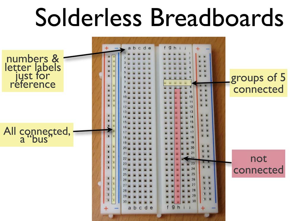
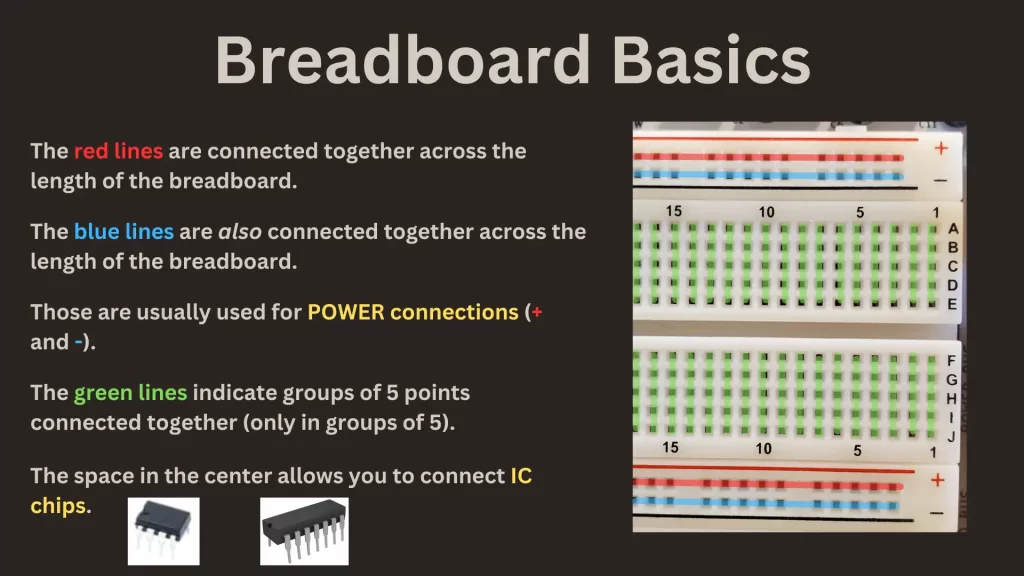
Most breadboards have power rails running along the sides. These are those long strips of connected holes, usually marked with '+' and '-' symbols (or red and blue lines, respectively), allowing you to easily distribute power throughout your circuit. The spacing between the power rails and the main section of the breadboard also typically follows the 0.1-inch standard, allowing components to easily bridge the gap and connect to power.
While the spacing within the power rails themselves is generally 0.1 inches, the distance between the power rail and the main prototyping area can vary slightly between different breadboard models. However, it's almost always designed to accommodate common component sizes, meaning you can usually plug a resistor or capacitor directly from the power rail to a nearby row of holes in the main area.
Its important to note that cheaper or smaller breadboards might deviate slightly from these standards. Always double-check the dimensions, especially if you're working with tightly spaced components. A quick measurement with a ruler or calipers can save you from compatibility issues later on.
Imagine your power rails are like the main roads of your circuit city. They need to be accessible from all areas, and the spacing is designed to facilitate easy connections to these vital arteries. Ignoring the spacing of the power rails is like trying to build a city without considering how people will get around — chaos will ensue!

Practical Tips for Working with Breadboard Spacing
4. Making the Most of the Breadboard Grid
Now that you know the spacing, let's talk about putting it to good use. Always make sure your components' leads are straight and properly aligned before plugging them into the breadboard. Forcing them in at an angle can damage the leads or the breadboard itself. Think of it like threading a needle — a little patience and precision will save you a lot of frustration. Straighten those leads!
When working with ICs, double-check the datasheet to identify pin numbers and functions correctly. Plugging an IC in backward can lead to disastrous results. Use a breadboard-friendly IC extractor tool to remove ICs. Never yank them out, or you risk bending the pins. Bent pins are like a paper jam in a printer annoying and easily avoidable.
Use jumper wires of the appropriate length to minimize clutter. Long, looping wires can make your circuit messy and difficult to troubleshoot. Short, direct connections are always preferable. It keeps your project tidy and makes it easier to debug. A clean breadboard is a happy breadboard!
Consider using a breadboard template or design tool to plan your circuit layout before you start building. This can help you visualize how components will fit together and identify potential spacing issues early on. It's like drawing a blueprint before building a house it helps you avoid costly mistakes later on.

How To Use A Breadboard And It Works Fx PCB
Troubleshooting Spacing Issues
5. When Things Don't Quite Fit
Sometimes, despite our best efforts, things don't quite fit as expected. Maybe you have a component with unusually thick leads, or perhaps your breadboard has slightly tighter spacing than usual. What do you do? Don't panic! There are solutions.
If a component's leads are too thick to fit comfortably in the breadboard holes, you can gently thin them using sandpaper or a file. Be careful not to remove too much material, or you might weaken the lead. However, always check to make sure you are not compromising the components function.
If you encounter inconsistencies in spacing between different breadboards, try to stick to one breadboard for the majority of your project, if possible. If you must combine multiple breadboards, be extra cautious about alignment and ensure that components are properly connected across the boundaries. Sometimes, a small adjustment to the components legs will help.
Always use a multimeter to verify connections. Even if a component looks like it's properly plugged in, there might be a break in the connection due to a loose or damaged contact inside the breadboard. A multimeter can quickly confirm whether a connection is solid or not, helping you pinpoint the source of your problem.

FAQ
6. Your Burning Questions Answered
Still have questions about breadboard spacing? Here are a few frequently asked questions to clear up any lingering confusion:
Q: What happens if I use the wrong spacing?A: If you force components into a breadboard with incorrect spacing, you risk damaging the components' leads or the breadboard itself. You might also create unreliable connections or even short circuits. It's generally best to avoid using components that don't fit the standard 0.1-inch grid.
Q: Are all breadboards created equal in terms of spacing accuracy?A: No, unfortunately not. Cheaper breadboards sometimes have slightly less precise spacing than more expensive ones. It's always a good idea to test the spacing with a few components before starting a major project.
Q: Can I use a breadboard with a different spacing standard?A: While breadboards with non-standard spacing exist, they are much less common and may be difficult to work with, especially if you're using standard DIP ICs. It's generally best to stick to breadboards that adhere to the 0.1-inch grid.
Q: What if I need to connect a component that doesn't fit the 0.1-inch spacing?A: You can use jumper wires to bridge the gap. Solder wires to the component's leads and plug the other ends of the wires into the breadboard. This allows you to connect components with non-standard spacing to your breadboard circuit.
So there you have it! A comprehensive guide to breadboard spacing. With this knowledge, you're well-equipped to tackle your next electronics project with confidence and precision. Happy breadboarding!